
Introduction
When building applications, it is essential to ensure business continuity by establishing high availability and disaster recovery mechanisms. This requires implementing a resilient disaster recovery framework capable of swiftly restoring operations in the event of an outage.
For years, organizations have relied on Oracle Exadata Database Service, Oracle’s premier disaster recovery technologies, to support mission-critical applications, whether on-premises or within Oracle Cloud Infrastructure (OCI). Now, Oracle Exadata Database Service on Oracle Database@Azure brings the same industry-leading performance, feature set, and price parity as Exadata on OCI. It leverages Microsoft Azure’s availability zones (AZs) and regions to provide low latency to Azure’s applications on top of unmatched high availability and disaster recovery capabilities, ensuring seamless operations during maintenance and in the event of disruption.
Architecture
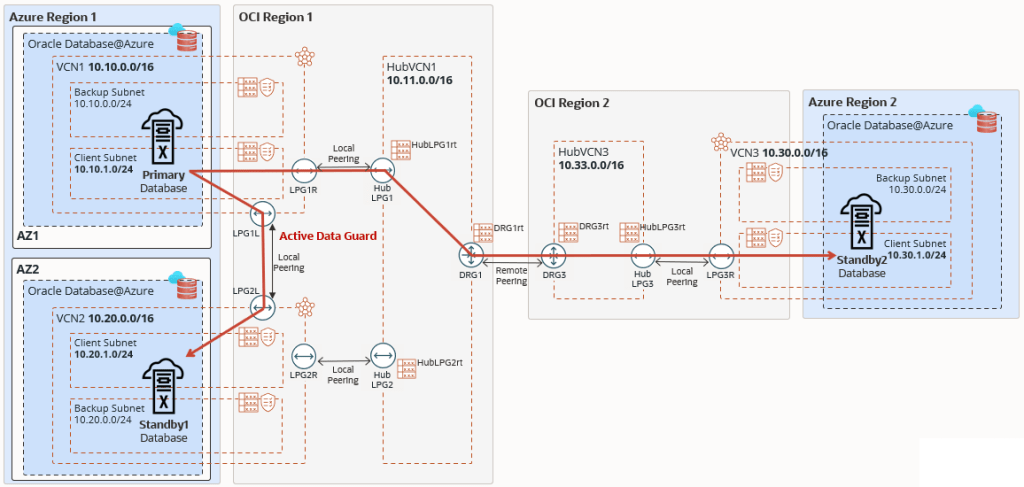
This architecture shows Oracle Exadata Database Service on Oracle Database@Azure in a disaster recovery topology using two standby databases, a local standby across zones, and a remote standby across regions.
For data protection, the Oracle Database is running in an Exadata virtual machine (VM) cluster in the primary region, with Oracle Active Data Guard replicating the data to two standby databases running on two Exadata VM clusters, the first in the same region but in a different zone (local standby), and the second in a different region (remote standby).
A local standby is ideal for failover scenarios, offering zero data loss for local failures while applications continue operating without the performance overhead of communicating with a remote region. A remote standby is typically used for disaster recovery or to offload read-only workloads. With multiple availability zones (AZs), the customer can leverage Azure multi-AZ application tier deployment to build a reliable solution and replicate the application tier to the standby location.
You can route Active Data Guard traffic through the Azure network. However, this architecture focuses on Active Data Guard network traffic through the OCI network to optimize network throughput and latency.
The Oracle Exadata Database Service on Oracle Database@Azure network is connected to the Exadata client subnet using a Dynamic Routing Gateway (DRG) managed by Oracle. A DRG is also required to create a peer connection between Virtual Cloud Networks (VCNs) in different regions. Because only one DRG is allowed per VCN in OCI, a second VCN acting as a Hub VCN with its own DRG is required to connect the primary and standby VCNs in each region. In this example:
- The primary Exadata VM cluster is deployed in
Region 1, zone 1inVCN1with CIDR 10.10.0.0/16. - The hub VCN in the
region 1isHubVCN1with CIDR 10.11.0.0/16. - The first standby Exadata VM cluster is deployed in
Region 1, zone 2inVCN2with CIDR 10.20.0.0/16. - The hub VCN is the same as the hub VCN for the primary database,
HubVCN1as it resides in the same region. - The second standby Exadata VM cluster is deployed in
Region 2inVCN3with CIDR 10.30.0.0/16. - The hub VCN in the remote standby
region 2isHubVCN3with CIDR 10.33.0.0/16.
No subnet is required for the Hub VCNs to enable transit routing, therefore these VCNs can use very small IP CIDR ranges. The VCNs on the OCI child site are created after the Oracle Exadata Database Service VM clusters on Oracle Database@Azure have been created for the primary and standby databases.
Recommendations
Use the following recommendations as a starting point when performing disaster recovery for Oracle Exadata Database Service on Oracle Database@Azure. Your requirements might differ from the architecture described here.
- Use Active Data Guard for comprehensive data corruption prevention with automatic block repair, online upgrades and migrations, and offload workload to standby with read-mostly scale-out.
- Enable Application Continuity to mask database outages during planned and unplanned events from end-users and ensure uninterrupted applications.
- Set up automatic backup to Oracle Database Autonomous Recovery Service (in Azure or OCI) even though the data is protected by Oracle Data Guard to minimize the backup workload on the database by implementing the incremental forever backup strategy that eliminates weekly full backups. Alternatively, customers can use OCI Object Storage for automatic backups.
- Enable backups from standby to achieve backup replication across regions.
- Use OCI Full Stack DR to orchestrate database switchover and failover operations.
- Use OCI Vault to store the database’s Transparent Data Encryption (TDE) keys using customer-managed keys.
Considerations
When performing cross-regional disaster recovery for Oracle Exadata Database Service on Oracle Database@Azure, consider the following.
- When Exadata VM clusters are created in the Oracle Database@Azure child site, each VM cluster is created within its own Oracle Cloud Infrastructure virtual cloud network (VCN). Oracle Data Guard requires that the databases communicate with each other to ship redo data. The VCNs must be peered to enable this communication. Hence, the Exadata VM cluster VCNs must not share overlapping IP CIDR ranges.
- Preparation for a disaster scenario requires a comprehensive approach that considers different business requirements and availability architectures and that encompasses those considerations in an actionable, high availability (HA) and disaster recovery (DR) plan. The scenario described here provides guidelines to help select the approach that best fits your application deployment by using a simple but effective failover for the disaster recovery configuration in your Oracle Cloud Infrastructure (OCI) and Microsoft Azure environments.
- Oracle Cloud Infrastructure is the preferred network for achieving better performance, measured by latency and throughput, and for achieving reduced cost, including the first 10 TB/Month egress for free.
Deploy
To configure the network communication between availability domains and regions shown in the above architecture diagram, complete the following high-level steps.
Primary Region (Region 1)
1. Add the following ingress rules to the Security List of the client subnet of VCN1 to allow incoming traffic from VCN2 and VCN3.
| Stateless | Source | IP Protocol | Source Port Range | Destination Port Range | Allows | Description |
|---|---|---|---|---|---|---|
| No | 10.20.0.0/16 | TCP | 1521 | 1521 | TCP traffic for ports: 1521 | allow ingress from VCN2 |
| No | 10.30.0.0/16 | TCP | 1521 | 1521 | TCP traffic for ports: 1521 | allow ingress from VCN3 |
2. Add the following ingress rules to the Security List of the client subnet of VCN2 to allow incoming traffic from VCN1 and VCN3.
| Stateless | Source | IP Protocol | Source Port Range | Destination Port Range | Allows | Description |
|---|---|---|---|---|---|---|
| No | 10.10.0.0/16 | TCP | 1521 | 1521 | TCP traffic for ports: 1521 | allow ingress from VCN1 |
| No | 10.30.0.0/16 | TCP | 1521 | 1521 | TCP traffic for ports: 1521 | allow ingress from VCN3 |
3. Create Virtual Cloud Network HubVCN1 with CIDR 10.11.0.0/16.
4. Create Local Peering Gateways HubLPG1 and HubLPG2 in Virtual Cloud Network HubVCN1.
5. Create Local Peering Gateways LPG1R and LPG1L in Virtual Cloud Network VCN1.
6. Create Local Peering Gateways LPG2R and LPG2L in Virtual Cloud Network VCN2.
7. Establish the local peering connection between LPG1R and HubLPG1.
8. Establish the local peering connection between LPG2R and HubLPG2.
9. Establish the local peering connection between LPG1L and LPG2L.
10. Add route rules to the Route Table of the client subnet of VCN1 to forward traffic targeted for VCN2 to LPG1L and forward traffic targeted for VCN3 to LPG1R.
| Destination | Target Type | Target | Route Type | Description |
|---|---|---|---|---|
| 10.20.0.0/16 | Local Peering Gateway | LPG1L | Static | traffic to VCN2 |
| 10.30.0.0/16 | Local Peering Gateway | LPG1R | Static | traffic to VCN3 |
11. Add route rules to the Route Table of the client subnet of VCN2 to forward traffic targeted for VCN1 to LPG2L and forward traffic targeted for VCN3 to LPG2R.
| Destination | Target Type | Target | Route Type | Description |
|---|---|---|---|---|
| 10.10.0.0/16 | Local Peering Gateway | LPG2L | Static | traffic to VCN1 |
| 10.30.0.0/16 | Local Peering Gateway | LPG2R | Static | traffic to VCN3 |
12. Create Route Tables HubLPG1rt and HubLPG2rt in HubVCN1.
13. Associate Route Table HubLPG1rt to Local Peering Gateway HubLPG1.
14. Associate Route Table HubLPG2rt to Local Peering Gateway HubLPG2.
15. Create Dynamic Routing Gateway DRG1.
16. Create Route Table DRG1rt in HubVCN1.
17. Add two route rules to Route Table DRG1rt: One to forward traffic targeted for VCN1 to HubLPG1 and a second route rule to forward traffic targeted for VCN2 to HubLPG2.
| Destination | Target Type | Target | Route Type | Description |
|---|---|---|---|---|
| 10.10.0.0/16 | Local Peering Gateway | HubLPG1 | Static | traffic to VCN1 |
| 10.20.0.0/16 | Local Peering Gateway | HubLPG2 | Static | traffic to VCN2 |
18. Attach DRG1 to HubVCN1. Choose “Autogenerated Drg Route Table for VCN attachments”, select existing Route Table DRG1rt, and choose “VCN CIDR blocks”.
19. Create a Remote Peering Connection in DRG1, named RPC1.
20. Add a route rule to HubLPG1rt to forward traffic targeted for VCN2 and VCN3 to DRG1.
| Destination | Target Type | Target | Route Type | Description |
|---|---|---|---|---|
| 10.30.0.0/16 | Dynamic Routing Gateway | DRG1 | Static | traffic to VCN3 |
21. Add a route rule to HubLPG2rt to forward traffic targeted for VCN2 and VCN3 to DRG1.
| Destination | Target Type | Target | Route Type | Description |
|---|---|---|---|---|
| 10.30.0.0/16 | Dynamic Routing Gateway | DRG1 | Static | traffic to VCN3 |
Standby Region (Region 2)
1. Add the following ingress rules to the Security List of the client subnet of VCN3 to allow incoming traffic from VCN1 and VCN2.
| Stateless | Source | IP Protocol | Source Port Range | Destination Port Range | Allows | Description |
|---|---|---|---|---|---|---|
| No | 10.10.0.0/16 | TCP | 1521 | 1521 | TCP traffic for ports: 1521 | allow ingress from VCN1 |
| No | 10.20.0.0/16 | TCP | 1521 | 1521 | TCP traffic for ports: 1521 | allow ingress from VCN2 |
2. Create Virtual Cloud Network HubVCN3 with CIDR 10.33.0.0/16.
3. Create Local Peering Gateway HubLPG3 in Virtual Cloud Network HubVCN3.
4. Create Local Peering Gateway LPG3R in Virtual Cloud Network VCN3.
5. Establish the local peering connection between LPG3R and HubLPG3.
6. Add route rules to the Route Table of the client subnet of VCN3 to forward traffic targeted for VCN1 and VCN2 to LPG3R.
| Destination | Target Type | Target | Route Type | Description |
|---|---|---|---|---|
| 10.10.0.0/16 | Local Peering Gateway | LPG3R | Static | traffic to VCN1 |
| 10.20.0.0/16 | Local Peering Gateway | LPG3R | Static | traffic to VCN2 |
7. Create Route Table HubLPG3rt in HubVCN3.
8. Associate Route Table HubLPG3rt to Local Peering Gateway HubLPG3.
9. Create Dynamic Routing Gateway DRG3.
10. Create Route Table DRG3rt in HubVCN3.
11. Add a route rule to DRG3rt to forward traffic targeted for VCN3 to HubLPG3.
| Destination | Target Type | Target | Route Type | Description |
|---|---|---|---|---|
| 10.30.0.0/16 | Local Peering Gateway | HubLPG3 | Static | traffic to VCN3 |
12. Attach DRG3 to HubVCN3. Choose “Autogenerated Drg Route Table for VCN attachments”, select existing Route Table DRG3rt, and choose “VCN CIDR blocks”.
13. Create a Remote Peering Connection in DRG3, named RPC3.
14. Establish remote peering connection between RPC1 (region 1) and RPC3 (region 2).
16. Add two route rules to HubLPG3rt to forward traffic targeted for VCN1 and VCN2 to DRG3.
| Destination | Target Type | Target | Route Type | Description |
|---|---|---|---|---|
| 10.10.0.0/16 | Dynamic Routing Gateway | DRG3 | Static | traffic to VCN1 |
| 10.20.0.0/16 | Dynamic Routing Gateway | DRG3 | Static | traffic to VCN2 |
